• Welcomes to Kumbakonam City

    Kumbakonam is one of the oldest towns in Tamilnadu and is famous for its Mahamaham festival. In the 7th Century it was the Capital of Chola Kings. Kumbakonam, the famous temple town of South India, is picturesquely located amidst the two rivers, Cauvery and Arasalar. Read more
  • Shoping at kumbakonam

    Kumbakonam is a Special Grade Municipal Town and second biggest town in terms of administrative status in Thanjavur District. Kumbakonam, being the headquarters of Kumbakonam Taluk, had different names like Kudanthai, Kudamooku and Baskarashetram from time immemorial.. Read more
  • Kumbakonam Temples

    Kumbakonam is known for its temples and mathas (monasteries). There are around 188 Hindu temples within the municipal limits of Kumbakonam... Read more

Gujarat Solar Industry Drivers


I think many of you who are reading this blog would be also interested in discussing what is driving the solar energy market. Frankly, there are many drivers, both at macro and micro level but still the market is not pushing as we had expected. Everyone nowadays puts the blame on "Global Recession" for lower rate of investments in solar energy sector. But some companies such as Suryachakra groupTata and very recently the Clinton Foundation have planned a huge investment in Gujarat's soalr energy sector. This is definately going to reap them benefits as in such times we get labor and materials at a cheap rate compared to when the economy is doing well. Think about it.

The key drivers according to me are:

Demand for Energy
> The accelerated pace of industrialization creates a massive demand for energy and corresponding investment into energy generation infrastructure and capacity
> In the first 8 months of this year, at least 80% of electric power generation in Indiacame from coal fired power plants
Economics
> Government policy has been to encourage cost reduction via the localization of Solar module manufacturing as well as awarding concession projects
Pollution Concerns
> India is beginning to address its serious pollution problem
> One solution has been to reduce the use of coal fired power plants which release tons of harmful carbon into the environment
Government Support
> The central government has supported Solar industry growth aggressively via ambitious targets for installed capacity as well as Solar power related regulations to incentivize growth in infrastructure
Environmental concerns
> Kyoto Protocol obliges members to reduce carbon emissions in light of the harmful effects of greenhouse gas on the global climate
> In newly industrialized countries, the main concern has been mitigating the pollutive effect of burning fossils fuels
> Solar power is the obvious alternative due to its minimal impact on the environment
Need for a stable, sustainable resource
> Demand for energy is predicted to be almost 60% higher in 20 years whereas the supply of fossil fuel is soaring
> Major concerns exist over the reliance on imports as well as unstable prices of non renewable energy
> Solar, on the other hand is an indigenous and unlimited resource
Commodity prices set to keep rising
> Average global industrial electricity prices have increased by 46% between 1998 and 2006, while average global household electricity prices have increased 42% over that time
Dramatic fall in cost of Solar energy production
> The cost of Solar energy has more than halved over the last 20 years(1)
- In the early 1980s, when the first utility-scale PV modules were installed, Solar-generated  electricity cost as much as 60 cents per kilowatt-hour. Today, state-of-the-art Solar  power plants can generate electricity for less than 15 cents/kWh(2)
> This cost is comparable to that of non renewable resources, especially after factoring the external costs of fossil fuel energy
e.g. new coal energy production costs approximately 5 – 9 cents per kwH
Significant improvement in technology
> Capacity, efficiency and visual design of Solar PV modules have improved dramatically
> A modern Solar Module is not only space efficient, but produces 20 more times electricity than what was available 20 years ago

Solar Energy Ideas


Solar Energy Ideas thumbnail
Solar energy is a clean, easy-to-use, free renewable source of power.
         In "Solar Energy Projects for the Evil Genius," Gavin Harper describes how energy is used in the developed world, with 58 percent of energy being spent on residential space heating, another 24 percent on heating water and 13 percent on electricity. Solar energy is a clean, easy-to-use, free renewable source of power. You can capture the sun's energy and store it for use when needed, reducing or eliminating reliance on expensive polluting fossil fuels. Does this Spark an idea?


Solar-Powered Fountain

  •                   For a beautiful, energy-efficient water feature in the garden, landscape or backyard, put together a solar-powered fountain. A submersible pump, a small solar array that produces enough energy to power the pump and a decorative fountain are connected for a water display that energy from the sun sustains for free.

Solar Battery Charger

  •                Use the power of the sun to charge your rechargeable batteries, and you won't have to root around in the junk drawer for fresh batteries ever again. Solar battery chargers are available commercially, but you can easily build one with a few simple materials like an AA battery holder, a nine-volt batter clip, a housing with an integral battery holder (optional), eight solar cells and an IN5818 Schottky diode. Hooked up with a simple schematic and positioned to catch the sun's rays, this unit charges batteries, saves money and is a source of free energy.

    Solar Attic Vent Fan

    •           You can install a solar attic vent fan in about a day with simple tools, and you'll save big on your home's summer energy costs, or you'll save year-round if you live in a warm climate. Attics can trap and store a lot of heat, forcing your home's cooling system to work harder and costing you more in electric bills. A solar fan runs on the free energy of the sun to move that hot trapped air out of your attic.

    Sun Room

    • Not only do sun rooms provide some extra living space, but they're a valuable solar energy device. Positioned properly to capture the most sun, even in winter, these rooms capture and store the sun's radiant heat. The best-engineered sun rooms distribute that captured heat to the rest of the house, reducing heating bills and increasing comfort throughout the building.

    Photo-Voltaic System

    •               If you want to make a large-scale investment in your home and in solar energy or if you're building a new home with photo-voltaic technologies, installing a full-scale photo-voltaic system will reap big rewards. Whole-house solar energy systems not only get your electric, water heating and space heating and cooling off the grid, but they can also get you plugged into the grid by allowing you to sell your extra energy to utility companies. That's free energy for your home and some to share with the community, if you're willing and able to invest in the latest solar technologies.


A Solar Power Station


                    Solar cells are often used in large quantities to form an array which can produce significant amounts of energy. These solar power stations are very rare in this country but are more common elsewhere, such as in North America. Arrays generally run the cells in series/parallel with each other so that the voltage output is limited to between 12 and 50 volts. This is done to minimize power losses and also for safety.
Image taken from www.darvill.clara.net without permission
           The daily energy output from a photovoltaic panel will vary according to factors such as season, weather, orientation and location. On average, in summer, a panel will produce about five times it's rated power output in watt hours per day and in winter twice that amount. For example, in summer a 50 watt panel will produce approximately 250 watt hours of energy.
Trackers are often used in solar power stations which keep the panels permanently facing the Sun. These can almost double the output of an array but other factors such as cost and increased complexity need to be considered when deciding if they are economically viable. The graph below compares power output for a tracked and a non-tracked array.
Image taken from http://acre.murdoch.edu.au/refiles/pv/text.html without permission
                  Solar power stations often require some type of energy storage when the Sun is not shining or during cloudy periods. Special lead acid batteries are used which can discharge half their energy several thousand times before they deteriorate. Each battery is usually 2V and a number of batteries are used to give the necessary power rating.
Inverters are also needed to transform low voltage DC power into high voltage AC power. Backup or auxiliary sources of power are also needed for when it is not economical to provide battery storage for long periods of time such as during extended cloudy periods. Wind generators can be used, as can small petrol or diesel generators.

How they work


              One of the major components of solar cells is silicon, which has several interesting properties allowing it to be a very useful material in solar cells. Pure silicon forms a crystalline structure with each atom bonding to its four nearest neighbours.
    Image taken from http://library.thinkquest.org without permission
                    Pure silicon is a relatively poor conductor because all the electrons are locked up in the crystalline structure. For a solar cell, the silicon has some impurities present such as some phosphorus atoms. Phosphorus has five electrons in it's outer shell so it is able to form bonds with four neighbouring phosphorus atoms, but it also has one electron which is not used in bonding.
When energy is added to pure silicon, such as in the form of heat, some electrons can break away from their bonds and leave a hole behind. These electrons, known as free carriers, will then move through the crystal looking for another hole to fill. In pure silicon, there are so few of them however that they are of very little use.
However, when energy is added to silicon with some phosphorus impurities, many extra phosphorus electrons can become free carriers, as they are not used in bonding. The process of adding impurities is called doping and if phosphorus is used, the resulting material is called N-type silicon (N for negative). This N-type silicon is a much better conductor than pure silicon.
The other part of a solar cell is P-type silicon (P for positive). This silicon has been doped with boron. Boron only has three electrons in it's outer shell so this silicon has extra holes instead of extra electrons. Holes are just the absence of electrons so they have a positive charge and can also move around.
When the N-type and the P-type layers are in contact with each other, all the free electrons on the N-side try and fill all the holes on the P-side. When the holes and the electrons mix at the junction between the two layers, the neutrality of the silicon is disrupted. At the junction, the holes and electrons mix and form a barrier. This makes it harder for the electrons to cross to the P-side and an equilibrium is reached where an electric field separates the two sides.
Image taken from http://science.howstuffworks.com without permission
                     When light (as photons) hits the cell, each photon with sufficient energy will free one electron and also result in one hole being formed. If this occurs close to the electric field, the field will cause the electron to go to the N-side and the hole to go to the P-side. This will cause a disruption of electrical neutrality and if a current path is present, electrons will flow along this to fill the holes which were sent to the P-side. This flow of electrons provides the current. The cell's electric field provides the voltage so together we have power (the product of current and voltage).

1.2 MW Marysville Rice Dryer Solar Installation


The Mathews Rice Dryer is a 6th generation rice drying facility operated by the Mathews family in Marysville, CA. A 1.2 MW solar installation was built to help offset nearly 60 percent of their annual electricity usage.
1.2 MW Marysville Rice Dryer Solar Installation1.2 MW Marysville Rice Dryer Solar Installation
1.2 MW Marysville Rice Dryer Solar Installation1.2 MW Marysville Rice Dryer Solar Installation1.2 MW Marysville Rice Dryer Solar Installation1.2 MW Marysville Rice Dryer Solar Installation
Location
Marysville CA 95901
United States
Date Installed04/2012
Total Size1200.00 kW
CivicSolar partnered with the Mathews Rice Farm and Rice Dryer to build a 1.2 MW solar power plant.   The system will provide solar power that will offset more than 60 percent of the facility’s electric usage.
Mathews Rice Dryer is one of the oldest and most established rice drying facilities in California.  It is operated by the Mathews family of  Marysville who have been working the land for 6 generations.   With over 2,000 MWhr of annual electricity use the operation was looking to offset its energy costs for drying rice while investing in the future of both its community and its facility.  
The project utilizes Astronergy solar panels, PV Powered inverters, Sunlink combiner boxes and a ground mount racking solution built around stut and Cooper B-line clamps.   This project is a model for what forethought and planning can provide to help bring about sustainable rice farming practices while generating a positive return on investment.  

Moser Baer plans to restructure over Rs1,800 cr term debt


New Delhi: Solar cell maker Moser Baer plans to restructure over Rs1,800 crore of its term debt as the company looks to strengthen its abilities to leverage future opportunities in the growing sector.
“We are looking at restructuring over Rs1,800 crore of term debt that the company has through corporate debt restructuring programme. This is almost half of the total Rs3,500 crore debt,” Moser Baer group CFO Yogesh Mathur said.
Restructuring is seen as an ideal solution to strengthen the company’s abilities to leverage future opportunities, he added.
He cited a McKinsey report which suggests the solar industry is likely to install an additional 400-600 GW of photovoltaic (PV) capacity between now and 2020 globally. Though the global demand for solar power is still high, the growth is expected to be flat this year.
Rapidly falling prices of solar panels and components has also impacted the profitability of solar cell makers, with companies like Solar Millennium and Solon SE filing for bankruptcy.
Moser Baer is also in discussions with banks for refinancing its outstanding foreign currency convertible bonds (about $88.5 million as nominal value). “The restructuring is happening by realigning it with Moser Baer India Ltd’s cash flows,” Mathur said.
Banks are positive about the company’s future plans and Moser Baer is looking forward to speedy completion of the debt restructuring and thereafter, to consolidate business and cash flows, he added.
The company narrowed its loss for the quarter ended 31 March 2012 to Rs59.60 crore from a loss of Rs131.20 crore in the same quarter last fiscal year. Total income from operations increased to Rs462.33 crore in the reported quarter from Rs458.95 crore in the year-ago period.
The company is bullish on the solar industry as the global PV market is forecast to witness substantial growth on account of higher installations anticipated in key markets such as the US, Germany and China. The industry witnessed a 76% year-on-year growth in PV installations during 2011, as per a EPIA - Global Market Outlook 2016 report.

78 kW Caguas, Puerto Rico Hotel Solar Installation

This 78 kW hotel roof mounted solar array in the fantastically sunny Caguas, Puerto Rico, is able to provide 50% of the hotel's power needs.
78 kW Caguas, Puerto Rico Hotel Solar Installation78 kW Caguas, Puerto Rico Hotel Solar Installation

Location
CaguasPR 00725
United States
18° 27' 3.5136" N66° 3' 22.05" W
Date Installed08/2012
Total Size78.00 kW
Profile visibilityPublic

This 78 kW hotel roof mounted solar array in the fantastically sunny Caguas, Puerto Rico, is able to provide 50% of the hotel's power needs. Designed by MFS Consulting Engineering , this project features Suniva 260 watt modules paired with the industry leading SMA Sunny Boy line of inverters.  

COMBINING SOLAR PHOTOVOLTAIC PANELS AND SOLAR THERMAL PANELS


                 It is possible to have both solar systems installed on your property. One providing electricity and the other providing hot water. For details of the individual systems, refer to the Solar PV and Solar Thermal sections.
Combining Solar PV and Solar Thermal Panels
So how does a combined system work in your home?

Solar thermal power plants


                           Many people associate solar electricity generation directly with photovoltaics and not with solar thermal power. Yet large, commercial, concentrating solar thermal power plants have been generating electricity at reasonable costs for more than 15 years. Volker Quaschning describes the basics of the most important types of solar thermal power plants.


                      Most techniques for generating electricity from heat need high temperatures to achieve reasonable efficiencies. The output temperatures of non-concentrating solar collectors are limited to temperatures below 200°C. Therefore, concentrating systems must be used to produce higher temperatures. Due to their high costs, lenses and burning glasses are not usually used for large-scale power plants, and more cost-effective alternatives are used, including reflecting concentrators.
\
                 The reflector, which concentrates the sunlight to a focal line or focal point, has a parabolic shape; such a reflector must always be tracked. In general terms, a distinction can be made between one-axis and two-axis tracking: one-axis tracking systems concentrate the sunlight onto an absorber tube in the focal line, while two-axis tracking systems do so onto a relatively small absorber surface near the focal point (see Figure 1).

Concentration of sunlight
FIGURE 1. Concentration of sunlight using (a) parabolic trough collector (b) linear Fresnel collector (c) central receiver system with dish collector and (d) central receiver system with distributed reflectors
                   The theoretical maximum concentration factor is 46,211. It is finite because the sun is not really a point radiation source. The maximum theoretical concentration temperature that can be achieved is the sun’s surface temperature of 5500°C; if the concentration ratio is lower, the maximum achievable temperature decreases. However, real systems do not reach these theoretical maxima. This is because, on the one hand, it is not possible to build an absolutely exact system, and on the other, the technical systems which transport heat to the user also reduce the receiver temperatures. If the heat transfer process stops, though, the receiver can reach critically high temperatures.
 Parabolic Trough Power Plants

Parabolic trough power plants are the only type of solar thermal power plant technology with existing commercial operating systems until 2008. In capacity terms, 354 MWe of electrical power are installed in California, and a plenty of new plants are currently in the planning process in other locations.
The parabolic trough collector consists of large curved mirrors, which concentrate the sunlight by a factor of 80 or more to a focal line. Parallel collectors build up a 300–600 metre long collector row, and a multitude of parallel rows form the solar collector field. The one-axis tracked collectors follow the sun.
The collector field can also be formed from very long rows of parallel Fresnel collectors. In the focal line of these is a metal absorber tube, which is usually embedded in an evacuated glass tube that reduces heat losses. A special high-temperature, resistive selective coating additionally reduces radiation heat losses.
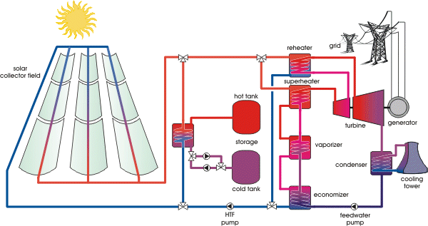
In the Californian systems, thermo oil flows through the absorber tube. This tube heats up the oil to nearly 400°C, and a heat exchanger transfers the heat of the thermal oil to a water steam cycle (also called Rankine cycle). A feedwater pump then puts the water under pressure. Finally, an economizer, vaporizer and superheater together produce superheated steam. This steam expands in a two-stage turbine; between the high-pressure and low-pressure parts of this turbine is a reheater, which heats the steam again. The turbine itself drives an electrical generator that converts the mechanical energy into electrical energy; the condenser behind the turbine condenses the steam back to water, which closes the cycle at the feedwater pump.
It is also possible to produce superheated steam directly using solar collectors. This makes the thermo oil unnecessary, and also reduces costs because the relatively expensive thermo oil and the heat exchangers are no longer needed. However, direct solar steam generation is still in the prototype stage.

 Guaranteed Capacity

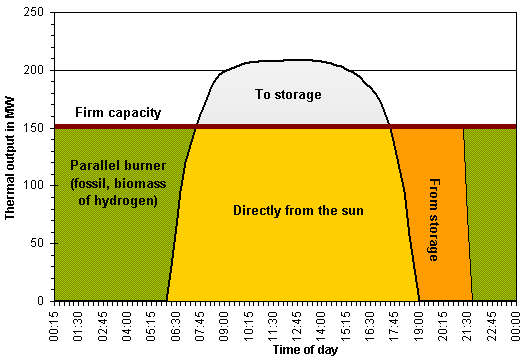
In contrast to photovoltaic systems, solar thermal power plants can guarantee capacity (see Figure 2). During periods of bad weather or during the night, a parallel, fossil fuel burner can produce steam; this parallel burner can also be fired by climate-compatible fuels such as biomass, or hydrogen produced by renewables. With thermal storage, the solar thermal power plant can also generate electricity even if there is no solar energy available.
Typical output of a solar thermal power plant
FIGURE 2. Typical output of a solar thermal power plant with two-hour thermal storage and backup heater to guarantee capacity
A proven form of storage system operates with two tanks. The storage medium for high-temperature heat storage is molten salt. The excess heat of the solar collector field heats up the molten salt, which is pumped from the cold to the hot tank. If the solar collector field cannot produce enough heat to drive the turbine, the molten salt is pumped back from the hot to the cold tank, and heats up the heat transfer fluid. Figure 3 shows the principle of the parabolic trough power plant with thermal storage.
Solar thermal trough power plant with thermal storage
FIGURE 3. Schematic of a concentrated solar thermal trough power plant with thermal storage
 Trough Power Plant Efficiencies

The efficiency of a solar thermal power plant is the product of the collector efficiency, field efficiency and steam-cycle efficiency. The collector efficiency depends on the angle of incidence of the sunlight and the temperature in the absorber tube, and can reach values up to 75%. Field losses are usually below 10%. Altogether, solar thermal trough power plants can reach annual efficiencies of about 15%; the steam-cycle efficiency of about 35% has the most significant influence. Central receiver systems such as solar thermal tower plants can reach higher temperatures and therefore achieve higher efficiencies.
 Solar Thermal Tower Power Plants

In solar thermal tower power plants, hundreds or even thousands of large two-axis tracked mirrors are installed around a tower. These slightly curved mirrors are also called heliostats; a computer calculates the ideal position for each of these, and a motor drive moves them into the sun. The system must be very precise in order to ensure that sunlight is really focused on the top of the tower. It is here that the absorber is located, and this is heated up to temperatures of 1000°C or more. Hot air or molten salt then transports the heat from the absorber to a steam generator; superheated water steam is produced there, which drives a turbine and electrical generator, as described above for the parabolic trough power plants. Only two types of solar tower concepts will be described here in greater detail.
 Open Volumetric Air Receiver Concept

The first type of solar tower is the open volumetric receiver concept (see Figure 4a). A blower transports ambient air through the receiver, which is heated up by the reflected sunlight. The receiver consists of wire mesh or ceramic or metallic materials in a honeycomb structure, and air is drawn through this and heated up to temperatures between 650°C and 850°C. On the front side, cold, incoming air cools down the receiver surface. Therefore, the volumetric structure produces the highest temperatures inside the receiver material, reducing the heat radiation losses on the receiver surface. Next, the air reaches the heat boiler, where steam is produced. A duct burner and thermal storage can also guarantee capacity with this type of solar thermal power plant.
 Pressurized Air Receiver Concept

The volumetric pressurized receiver concept (see Figure 4b) offers totally new opportunities for solar thermal tower plants. A compressor pressurizes air to about 15 bar; a transparent glass dome covers the receiver and separates the absorber from the environment. Inside the pressurized receiver, the air is heated to temperatures of up to 1100°C, and the hot air drives a gas turbine. This turbine is connected to the compressor and a generator that produces electricity. The waste heat of the gas turbine goes to a heat boiler and in addition to this drives a steam-cycle process. The combined gas and steam turbine process can reach efficiencies of over 50%, whereas the efficiency of a simple steam turbine cycle is only 35%. Therefore, solar system efficiencies of over 20% are possible.
Schematic of two types of solar thermal tower power plant
FIGURE 4. Schematic of two types of solar thermal tower power plant, showing (a) an open volumetric receiver with steam turbine cycle and (b) a pressurized receiver with combined gas and steam turbine cycle
 Comparing Trough and Tower

In contrast to the parabolic trough power plants, no commercial tower power plant exists at present. However, prototype systems – in Almería, Spain, in Barstow, California, US, and in Rehovot, Israel – have proven the functionality of various tower power plant concepts.
The minimum size of parabolic trough and solar tower power plants is in the range of 10 MWe. Below this capacity, installation and O&M costs increase and the system efficiency decreases so much that smaller systems cannot usually operate economically. In terms of costs, the optimal system size is in the range of 50–200 MWe.

 Dish-Stirling Systems

So-called Dish–Stirling systems can be used to generate electricity in the kilowatts range. A parabolic concave mirror (the dish) concentrates sunlight; the two-axis tracked mirror must follow the sun with a high degree of accuracy in order to achieve high efficiencies. In the focus is a receiver which is heated up to 650°C. The absorbed heat drives a Stirling motor, which converts the heat into motive energy and drives a generator to produce electricity. If sufficient sunlight is not available, combustion heat from either fossil fuels or biofuels can also drive the Stirling engine and generate electricity. The system efficiency of Dish–Stirling systems can reach 20% or more. Some Dish–Stirling system prototypes have been successfully tested in a number of countries. However, the electricity generation costs of these systems are much higher than those for trough or tower power plants, and only series production can achieve further significant cost reductions for Dish–Stirling systems.
Dish-Stirling prototype systems in Spain
 Solar Chimney Power Plants

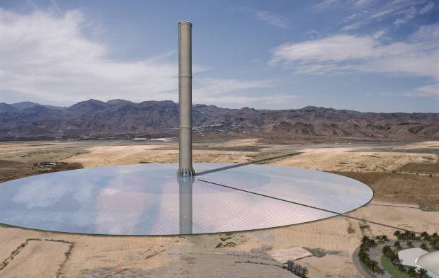
All three technologies described above can only use direct normal irradiance. However, another solar thermal power plant concept – the solar chimney power plant – converts global irradiance into electricity. Since chimneys are often associated negatively with exhaust gases, this concept is also known as the solar power tower plant, although it is totally different from the tower concepts described above. A solar chimney power plant has a high chimney (tower), with a height of up to 1000 metres, and this is surrounded by a large collector roof, up to 130 metres in diameter, that consists of glass or resistive plastic supported on a framework (see artist’s impression). Towards its centre, the roof curves upwards to join the chimney, creating a funnel.
The sun heats up the ground and the air underneath the collector roof, and the heated air follows the upward incline of the roof until it reaches the chimney. There, it flows at high speed through the chimney and drives wind generators at its bottom. The ground under the collector roof behaves as a storage medium, and can even heat up the air for a significant time after sunset. The efficiency of the solar chimney power plant is below 2%, and depends mainly on the height of the tower, and so these power plants can only be constructed on land which is very cheap or free. Such areas are usually situated in desert regions.
However, the whole power plant is not without other uses, as the outer area under the collector roof can also be utilized as a greenhouse for agricultural purposes. As with trough and tower plants, the minimum economical size of solar chimney power plants is also in the multi-megawatt range.

5 MW solar chimney power plant
Artist’s impression of a 5 MW solar chimney power plant SCHLAICH BERGERMANN SOLAR (SBS) GMBH, STUTTGART www.sbp.de
 Electricity Generation Costs

Due to the poor part-load behaviour of solar thermal power, plants should be installed in regions with a minimum of around 2000 full-load hours. This is the case in regions with a direct normal irradiance of more than 2000 kWh/m2 or a global irradiance of more than 1800 kWh/m2. These irradiance values can be found in the earth’s sunbelt; however, thermal storage can increase the number of full-load hours significantly.
The specific system costs are between €2000/kW and €5000/kW depending on the system size, system concept and storage size. Hence, a 50 MWe solar thermal power plant will cost €100–250 million. At very good sites, today’s solar thermal power plants can generate electricity in the range of €0.15/kWh, and series production could soon bring down these costs below €0.10/kWh.
The potential for solar thermal power plants is enormous: for instance, about 1% of the area of the Sahara desert covered with solar thermal power plants would theoretically be sufficient to meet the entire global electricity demand. Therefore, solar thermal power systems will hopefully play an important role in the world’s future electricity supply.

How to Convert an Old Water Heater to a Solar Water Heater


Billions of photons stream from the Sun to the Earth. When photons strike the Earth's surface atoms begin moving faster. The increased speed generates heat and is the theory behind thermal conduction. This is what solar power is based upon. Solar water heaters use no moving parts, just a heat collector box. This passive method can heat water up to 150 degrees Fahrenheit.

Difficulty:

Moderate Instructions
Hot water heater

Black spray paint
Copper piping or strong hose
Water supply fittings
Pressure release valve
2-by-4-inch lumber
Reflective insulation
Plywood sheets
Sheet of double paned glass
Window clips
Wood screws
Drill and drill bit

The Water Tank

1.Locate the water heater. Look in local junk yards or at homes being remodeled. Ask about pricing and choose a water heater in good condition for your price range.
2.Remove the outer enclosure. Remove the insulation. Remove the pipe fittings. You want only the metal tank that makes up the core of the heater. Discard and recycle the parts you removed according to local ordinances.
3.Fill the tank with water. Check for leaks. Empty the tank and rinse out any sediments.
4.Sand the tank exterior thoroughly. Spray the exterior with the black paint. Use multiple coats. The paint protects the metal from moisture while aiding the heat absorption.
5.Screw the water supply fittings to the old connections on top of the tank. You need one for cold water to flow from the house to the tank and the other to deliver hot water from the tank to the house. Install the drain spigot to one of the holes on the side of the tank. Install the pressure release valve near the fitting for the water supply. Plug the remaining unused holes in the tank.

Collector Box

1.Measure and cut the lumber to accommodate the size of the tank. Allow for a few inches clearance around the entire tank.
2.Build the collector box. Build two squares from the shorter lumber for the top and bottom. Use the longer lumber to make the sides.
3.Measure and cut three sections of plywood for the sides of the box. Measure and cut a square piece of plywood to be the base of the box.
4.Cut three lengths of 2-by-4-inch lumber to match the curve of the tank base. These become the supports. Attach the support lumber to the base sheet of plywood.
5.Stand the box up. Set the base sheet upside down over the top of the box. The supports should be facing the floor. Attach the base to the box with screws. Flip the box upright and set in place where the heater is going.

The Walls

1.Lower the water heater into the box. Rest the base on the supports squarely.
2.Measure and cut three sections of insulation 4 inches smaller than the plywood sheets on all sides. Lay insulation onto each sheet with the reflective side facing outward. Center the insulation and staple it into place.
3.Mount each of the three insulated sheets to the box to form the walls. Set the walls with the insulation facing the tank. Keep the south face wall open. The insulation should fit between the corners of the box. Attach each wall to the box with screws.
4.Attach the window clips to the inside edge of the open box side. Slide the appropriate glass piece into place from the top. Mount the smaller glass piece onto the top of the box. These will collect the sunlight.
5.Prime and paint all wood surfaces. This helps maintain the box durability against the elements. Caulk all the seams to retain heat and keep moisture out.

Attaching Heater

1.Attach the water lines from the house to the heater. Attach the overflow hose to the pressure release valve. Run the overflow hose out the bottom of the box.
2.Turn on the water. Fill the tank and test the lines.
3.Wait 24 hours for the water to heat up. This gives enough time for the heater to begin working.